Technology
The Riverbox crossflow turbine
An optimised, locally manufactured Banki-Michell crossflow turbine, engineered for the low-head, high-flow run-of-river conditions common in Zambian streams.
How it works
From flowing water to a working mini-grid
- 1
Intake
A screened intake guides part of the stream's flow into the Riverbox while debris is kept out.
- 2
Crossflow runner
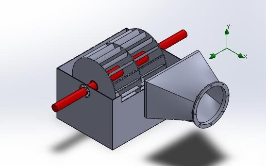
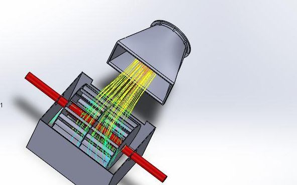
Water passes twice through a wide, multi-blade runner, converting the energy of high-volume, low-head flow into rotation at around 300 RPM.
- 3
Generator & control
A generator produces electricity; the controller keeps voltage and frequency stable.
- 4
Distribution
Power is delivered to nearby homes and businesses through a small local network.
Technical specifications
- Turbine type
- Atmospheric crossflow (Banki-Michell), radial multi-blade runner
- Design net head
- 1.0 – 10.0 metres
- Design flow rate
- ≥ 50 litres per second
- Rotational speed
- 300 RPM (nominal runner speed)
- Mechanical efficiency
- 79% (CFD-validated)
- Power output
- Prototype: 6.8 kW mechanical · Pilot targets: 5–10 kW electrical
Efficiency validated by computational fluid dynamics (CFD). Pilot figures are being confirmed through field validation.
Key innovations
Engineered for Zambian rivers and workshops
100% import substitution
Built in standard Zambian mechanical workshops from locally available steel grades and off-the-shelf transmission components, instead of imported generators and specialised runners.
Low-head optimisation
A wide, multi-blade runner extracts energy from high-volume, low-head rivers with drops down to 1 metre, minimising expensive civil works and dams.
Baseload power, 24/7
Continuous generation with no heavy battery storage (as with solar mini-grids) and no fuel logistics (as with diesel generators).
Design & validation
Simulated, analysed and drawn for fabrication
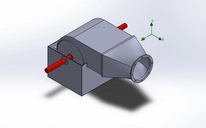
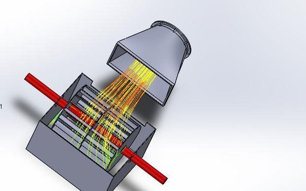
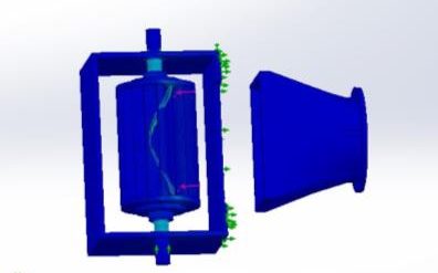
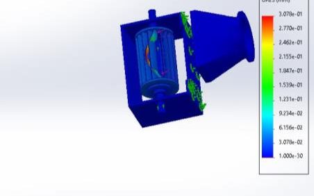
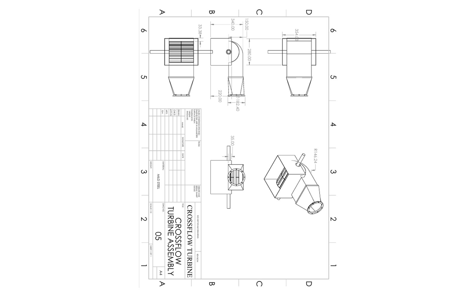
Riverbox has been modelled in CAD, its flow analysed with computational fluid dynamics (CFD), and its structure checked with finite element analysis (FEA).
Why micro-hydro?
Riverbox
- • Small intake, minimal civil works
- • Faster to install
- • Maintained locally
- • Runs day and night
Diesel generator
- • Ongoing fuel cost
- • Fuel must be transported in
- • Noise and emissions
- • Runs only when fuelled
Large hydro
- • Large dam and civil works
- • Years to build
- • High capital cost
- • Requires grid extension
What's next
A smart, monitored Riverbox
Future units will report RPM, voltage, current, water flow and energy output to a monitoring dashboard, so our engineers can spot issues early and plan maintenance before faults occur.
Help take Riverbox from pilot to production
Contribute to the development and deployment of Riverbox, or talk to us about investment and partnership.